@

max

Sunday

Chrysler Cv-joints Overhaul

How To Overhaul Cv-joints


Inner Cv-joints And Outer Cv-joints Replacing


Starting With Inner Cv-joints

Please Make Sure You take proper safety precautions. Don't Ignore Safety Note And Helpful Warnings.


Inner CV-Joint & Boot:--

Start with disconnecting the negative battery cable.
Remove the halfshaft and retaining clamps.
Slide the boot down the shaft away from the tri-pot housing.

NOTE
When separating the spider joint from the tri-pot joint housing, hold the rollers in place on the trunnions to prevent the rollers and needle bearings from falling away.


Carefully, slide the shaft/spider assembly from the tri-pot housing.
Remove the spider assembly-to-shaft snapring; then, slide the spider assembly off the shaft.

WARNING
If necessary, tap the spider assembly off the shaft using a brass drift; be careful not to hit the outer bearings.


Slide the boot off the shaft.

Thoroughly, inspect all parts for signs of excessive wear; if necessary, replace the halfshaft.

NOTE
Component parts are not serviceable and must be replaced as an assembly.


See below the diagram showing halfshaft inner tri-pot joint and snapring

Chrysler Halfshaft Tripod And Snap Ring.

For more help Another diagram is provided showing  View of the halfshaft boot, shaft and boot clamp
Chrysler Halfshaft boot and inner shaft Assembly

How To tightly secure Halfshaft boot clamp.Please note this,while reassembly it has to be that tight.
Securing the halfshaft boot clamp
Chrysler Halfshaft boot

Once the completely disassembly ios done.Inspect the parts.What ever looks dirty try cleaning and servicing it.If any part seems broken or damaged then it has to be replaced with new part.


Once all inspection is done continue with installation procedure.

Below is the procedure for How To install:

Slide the inner tri-pot boot clamp and boot onto the shaft; then, position the boot so that only the thinnest (sight) groove is visible on the shaft.

Install the spider assembly onto the shaft just far enough so that the snapring can be installed.

WARNING
If necessary, tap the spider assembly onto the shaft using a brass drift; be careful not to hit the outer bearings.


Install the snapring onto the shaft; make sure that the snapring is fully seated in the groove.

If installing a new boot, distribute 1 / 2 of the grease in the service package inside the tri-pot housing and the other 1 / 2 inside the boot.

Carefully, slide the spider assembly and shaft into the tri-pot housing.

Position the inner boot clamp evenly on the sealing boot.

Using the Crimper tool C-4975, place the tool over the clamp bridge, tighten the tool nut until the jaws are completely closed (face-to-face).

WARNING
The seal must not be dimpled, stretched or out of shape. If necessary, equalize the seal pressure and shape it by hand.


Position the boot onto the tri-pot housing retaining groove and install the retaining clamp evenly on the boot.

Using the Crimper tool C-4975, place the tool over the clamp bridge, tighten the tool nut until the jaws are completely closed (face-to-face).

Install the halfshaft into the vehicle.
The Diagram Showing How To Install Halfshaft In the vehicle
Chrysler Halfshaft Assembly Installation
The Above Procedure was for Inner Cv-joint.
And Now Comes The Details For 
Outer CV-Joint

Without fail take safety  Precautions.

Remove the following parts:-----
Disconnect the negative battery cable.
Remove the halfshaft and the retaining clamps.
Slide the boot down the shaft away from the CV-joint housing.
Remove the grease to expose the CV-joint-to-shaft retaining ring.
Spread the snapring ears apart and slide the CV-joint assembly off of the shaft.
Slide the boot off the shaft.

Thoroughly, clean and inspect all parts for signs of excessive wear; if necessary, replace the halfshaft.

NOTE
Component parts are not serviceable and must be replaced as an assembly.

Chrysler Outer Cv-joint Removal

Once the Parts are removed,view its condition,service and reuse the working parts.Replace the faulty damaged parts with good parts.
Then follow the Installation.

To install:

Slide the outer CV-joint boot clamp and boot onto the shaft; then, position the boot so that only the thinnest (sight) groove is visible on the shaft.

Slide the outer CV-joint assembly on the shaft, spread the snapring ears, position the CV-joint and verify that the snapring is fully seated in the shaft groove.

If installing a new boot, distribute 1 / 2 of the grease in the service package into the CV-joint housing and the other 1 / 2 inside the boot.

Position the outer boot clamp evenly on the sealing boot.

Using the Crimper tool C-4975, place the tool over the clamp bridge, tighten the tool nut until the jaws are completely closed (face-to-face).

WARNING
The seal must not be dimpled, stretched or out of shape. If necessary, equalize the seal pressure and shape it by hand.


Position the boot onto the CV-joint housing retaining groove and install the retaining clamp evenly on the boot.

Using the Crimper tool C-4975, place the tool over the clamp bridge, tighten the tool nut until the jaws are completely closed (face-to-face).

Install the halfshaft into the vehicle.

This details will help to remove and install Cv-joints,Halfshafts In Your Chrysler Vehicle.


How To Replace Automatic Transaxle

Automatic Transaxle Replacing On Chrysler 300M


For Manual Transaxle replacing click here

Automatic Transaxle Removal Procedure Is As follows:----

Don't Ignore The WARNING: 
Allowing the CV-joint assemblies to dangle unsupported, or pulling or pushing the ends, can damage boots or CV-joints. Always support both ends of the halfshaft to prevent damage or disengagement of the Tri-pot joint.


Before servicing the vehicle, make sure you take proper Precautions.

Remove or disconnect the following parts mentioned below:
  • Negative battery cable
  • Front wheels
  • Front caliper assembly from steering knuckle
  • Front brake rotor from the hub
  • Speed sensor cable routing bracket from strut assembly
  • Hub and bearing-to-stub axle retainer nut
Once the mentioned components are removed ...............
Install a puller tool onto the hub and bearing assembly and secure it into place using the wheel lug nuts.

Protect wheel stud threads by installing a wheel lug nut onto a wheel stud. Use a flat-bladed prying tool to prevent the hub from turning. Using the puller tool, force the halfshaft outer stub axle from the hub and bearing assembly.

2004 Chrysler 300m Front Halfshaft
Fig. Front halfshaft assemblies-2004 shown, others similar

How To Remove the Stub Axle Is Shown Below In the Diagram:----
Chrysler Stub Axle Replacement Diagram
Fig. Removing the stub axle from the front hub/bearing assembly-halfshaft service

Outer Cv-joint Has to be removed very carefully.The Diagram Below Shows How To Remove Cv-joint:

Chrysler Cv-joint Replacing
Fig. Be careful not to damage the threads for the axle nut when removing the outer CV-joint from the steering knuckle-halfshaft service

The Helpful Summary Of How To Exactly Perform This Disassembly:
Please Don't Ignore the Important Notifications And Warning Mentioned.
Dislodge the inner Tri-pot joint from the stub shaft retaining snapring on the transaxle. To do this, insert a prybar between the transaxle case and the inner Tri-pot joint and pry on Tri-pot joint.

NOTE
Do not try to remove the inner Tri-pot joint from the transaxle stub shaft at this time. Only disengage the inner Tri-pot joint from the retainer snapring.


Remove the strut assembly-to-steering knuckle attaching bolts from the strut assembly.

WARNING
The strut assembly-to-steering knuckle bolts are serrated (toothed) where they go through the strut assembly and steering knuckle. When removing the bolts, turn the nuts off the bolt; do not turn the bolts in the steering knuckle or damage to the steering knuckle will result.


Separate the top of the steering knuckle from the lower end of the strut.

Hold the outer joint assembly with one hand. Grasp the steering knuckle with the other hand and rotate it out and to the rear of the vehicle, until the outer CV-joint clears the hub and bearing assembly.

WARNING
When removing the outer CV-joint from the hub and bearing assembly, do not allow the flange disc on the hub and bearing assembly to become damaged. If this happens, dirt and water can enter the bearing, which will cause premature bearing failure.


Remove the halfshaft inner joint from the transaxle stub shaft by grasping the inner Tri-pot joint and the interconnecting shaft and pulling both pieces at the same time. Take care not to pull on the interconnecting shaft to remove or separation of the spider assembly will occur.

Once all the part is out then clean the dirty part,service the parts and replace the faulty worn out broken/damaged parts.

After that the simple and easy procedure To install:

Install the Tri-pot joint side of the halfshaft by performing the following procedure:

  • Replace the inner Tri-pot joint retaining circlip and O-ring seal on the transaxle stub shaft. These components are not reusable and must be replaced whenever the halfshaft is removed.
  • Apply an even coat of grease on the splines of the inner Tri-pot joint, where the O-ring seats against the Tri-pot joint.
  • Install the halfshaft through the hole in the splash shield. Grasp the inner joint in 1 hand and interconnecting shaft in the other. Align the inner Tri-pot joint spline with the stub shaft spline on the transaxle. Use a rocking motion with the inner Tri-pot joint to get it past the circlip on the transaxle stub shaft.
  • Continue pushing the Tri-pot joint onto transaxle stub shaft until it stops moving. The O-ring on the stub shaft should not be visible when the inner Tri-pot joint is fully installed. Check that the inner Tri-pot joint is locked in position by grasping the inner joint and pulling. If locked in position, the joint will not move on the stub shaft.


Hold the outer CV-joint assembly with one hand. Grasp the steering knuckle with the other and rotate it out and to the rear of the vehicle. Install the outer CV-joint into the hub and bearing assembly.
Install or connect the following:

  • Top of the steering knuckle into the strut assembly. Align the steering knuckle-to-strut assembly mounting holes.
  • Strut assembly-to-steering knuckle attaching bolts. Install the nuts to the attaching bolts and while holding the bolt heads, torque the nuts to 125 ft. lbs. (170 Nm). Turn the nuts on the bolts. DO NOT turn the bolts.
  • New hub and bearing assembly-to-stub shaft retainer nut. Tighten but do not torque the nut at this time.
  • Speed sensor cable routing bracket and screw
  • Brake rotor and caliper assembly; then, tighten the caliper guide pin bolts to 30 ft. lbs. (41 Nm)
  • Front wheels and lug nuts
  • Negative battery cable

Once all the process is done then test the brake.It should be firm tight like original.Pump the brakes until a firm pedal is obtained.

Apply the brakes and torque the new stub shaft-to-hub and bearing assembly retainer nut to 120 ft. lbs. (163 Nm).

WARNING
When tightening the stub shaft retaining nut, be careful not to exceed the maximum torque specification of 120 ft. lbs. (163 Nm). If this specification is exceeded, failure of the halfshaft could result.


Road test the vehicle to check for noise or vibration.

This Procedure will Help to Replace The Automatic Transaxle.


How To Remove Transaxle on Chrysler 300M?

Chrysler Transaxle Removal

4 Speed Transaxle Description:--


The 42LE four speed transaxle uses fully-adaptive controls. Adaptive controls are those which perform their functions based on real-time feedback sensor information. The transaxle is conventional in the use of hydraulically applied clutches to shift a planetary gear train. However, it uses electronics to control virtually all other functions. Note that the factory recommends that before attempting any repair on the 42LE four-speed automatic transaxle, always check for proper shift linkage adjustment. Also, check for diagnostic trouble codes with the Chrysler DRB scan tool.

Use MOPAR Type 7176 Automatic Transmission Fluid only. Do not substitute transaxle fluid. If the differential sump requires fluid, use 80W-90 petroleum based Hypoid gear lubricant.


Before servicing the vehicle, make sure you take proper Precautions.


CAUTION: Be careful of sharp edges cowl/wiper area.

Remove or disconnect the following: 

  • Negative battery cable
  • Wiper blades
  • Right and left wiper module covers
  • Steel cowl/strut support

  • Engine air inlet tube
  • Transaxle harness connectors at cowl area
  • Upper bell housing studs
  • Loosen clamps at intersection of rear exhaust system to front catalytic converter pipe
  • Rear exhaust from left catalytic converter pipe and right extension pipe
  • Rear exhaust system
  • Nuts securing the exhaust pipes to transaxle mount
  • Loosen clamp at right extension at right catalytic converter
  • Right extension
  • Crankshaft Position (CKP) sensor connector and remove sensor. The sensor is located on the upper right side of the transaxle bell housing.
  • Dipstick tube
  • Gear selector cable from the transaxle
  • Transmission range sensor connector
  • Input and output speed sensor connector
  • Transaxle cooler lines from the transaxle and plug them
  • Lower control arm pinch bolts
  • Lower control arms from steering knuckles by prying them out


Use a prybar to separate the inner tripod joints from the transaxle
  1. How To remove Halfshafts On Chrysler
    Fig. The halfshafts do not have to be completely removed from the vehicle.


Pull the bottom of the knuckles and halfshafts outward to allow clearance during transaxle removal. The halfshafts do not have to be completely removed from the vehicle. 

WARNING:  Do not let the halfshafts or CV-joints hang unsupported. Internal joint damage may result if allowed to hang free.
Remove or disconnect the following: 

NOTE:  Matchmark the installed position of the torque converter to the flex plate before removal.

Heated Oxygen Sensor (HO 2 S) wiring and left catalytic converter pipe.
Starter bolts and position it between the engine and transaxle. Do not disconnect the wiring or completely remove the starter.
Engine oil pan cooler.
Torque converter bolts and discard them. New bolts must be used during installation.
Use a transmission jack to slightly raise the transaxle, removing weight from the rear transaxle mount. 

    NOTE
    The crossmember bridge bolts are different lengths for each side, so note their locations during removal.


    NOTE
    Lower the rear of the transaxle to access to the bell housing bolts.

Rear crossmember bridge bolts
Rear mount adapter plate mounting bolts
Rear crossmember bridge, mount and adapter plate as an assembly

  • Side bell housing bolts
  • Dipstick tube from the transaxle and plug to prevent leakage
  • Solenoid/pressure switch assembly connector from the top of the transaxle
  • Transaxle by lowering it from the vehicle.


The procedure to install:

To prevent damaging the structural collar, hand-tighten all fasteners before torquing them to specifications.
If the torque converter is being replaced, apply a light coat of oil to the crankshaft pilot hole.
Check the drive plate for cracks before reinstalling the transaxle and replace the plate as necessary.
Use new torque converter-to-drive plate bolts, as different year models use different bolts.
Installation is the reverse of the removal procedure, noting the following torque specifications:

  • Converter-to-driveplate bolts: 65 ft. lbs. (88 Nm)
  • Driveplate-to-crankshaft: 70 ft. lbs. (95 Nm)
  • Engine-to-transaxle case bolts to 75 ft. lbs. (101 Nm)
  • Input and output speed sensor-to-case bolts: 20 ft. lbs. (27 Nm).

Fill the transaxle with fluid. Start the engine and allow it to idle for 2 minutes. Apply the parking brake and move the selector through each gear position, ending in N . Recheck the fluid level and add if necessary. Be sure the vehicle is level when refilling the transaxle. Use Mopar Type 9602 Automatic Transmission Fluid (ATF+4) only. Do not substitute transaxle fluid.
Check the transaxle or proper operation. Adjust the shift linkage, if necessary. Be sure the reverse lamps come on when in reverse.

This Guide Will Help to Remove And Install Transaxle.


How to replace sun visor on 2001 buick regal

Sun visor removed and replaced without damage


Buick Regal sunvisor replacing procedure is as follows:---

Rotate the sunshade so that the bottom edge is pointing straight down.
Remove the sunshade from the anchor.
How To Replace buick regal sun visor


Move the sunshade rearward, about 50 mm (2 inches) until the ridge on the sunshade stem (2) is flush to the slot in the flange (1).
Pull down on the free end of the sunshade until a rectangular slot (3) appears between the flange and the retainer bezel. Maintain this pressure for the next two steps.

The Visor is connected to plastic collar. Pull down the visor to separate the plastic collar on the end of the visor shaft from the plastic retaining clip in your headliner. Next thing is to bring the shaft to its exact angle.For that  insert a straight bit screw driver into the notch in the plastic collar and turn the visor till the stopper on the shaft rests against your screwdriver. This will lock the plastic collar to the shaft coming from the sun visor. Then turn the entire thing a little more (about 1/4 of a turn). this will allow the visor and collar to come out of the retaining clip. then with screwdriver pry the legs on the retaining clip so that it comes out of your headliner. And it will come out.

Important: The flat-bladed tool used to remove the sunshade must completely fill the slot on the sunshade flange. If there is any free play, the plastic flange will be distorted and the sunshade will not be released.

Once the above procedure is done Next .......
Insert a flat-bladed tool in the flange slot. Hold this tool in a vertical position and maintain an upward pressure on the tool equal to the downward pressure on the sunshade.
Quickly rotate the sunshade rearward approximately 100 mm (4 in). At this position you will feel a first disengagement.
Maintain the upward pressure on the flat-bladed tool and now press upward on the free end of the sunshade. Then continue to rotate the sunshade towards the side door glass.
Remove the flat-bladed tool and pull down on the front of the sunshade arm to separate it from the bezel.
How To Remove Buick Sun visor

Disconnect electrical connector (3).

This will help.
Thanks.

Pontiac Vacuum Hose Diagram

Vacuum Hose Pump Diagram Pontiac


For Complete Vacuum hose diagram

Fuel pressure regulator
Intake Manifold
PCV Valve
Brake Booster
EVAP Canister Purge Valve
Throttle Body

FOR PREVIOUS VACUUM HOSE DIAGRAM CLICK HERE


1996 3.8L (BRN) Engine-Federal and California:--
Pontiac Vacuum hose Diagram

-----------

1996 3.8L (BRG) Engine-Federal and California:--


1996 3.8L (BRF) Engine-Federal and California


Pontiac Vacuum hose line


This Details Will Help.

Ford Engine Wiring Diagram

Wiring Diagram Ford Engine Ignition


The wiring diagram shows details for ford crankshaft sensor,ignition coil,sparkplug firing order details and much more:

For Previous Wiring Diagram Click Here

-----------
Diagram number 2:---
Engine Ignition System Wiring Diagram

-----------
Diagram number 3:---
image

-----------
The firing order diagram:---
Ford Escape Ignition Spark plug Firing Order

-----------
NOTE:-- 

Ignition timing is controlled by the Powertrain Control Module (PCM). No adjustment is necessary or possible.


For Sparkplug Testing,gapping and replacement details

How To Replace Headlight Switch On Dodge Caravan

Dodge Caravan Headlight Switch


For Headlight Switch Removal Diagram Click Here

For Removal Procedure Follow Reading As Follows:
Disconnect the negative battery cable.

Remove the instrument cluster bezel.

Disconnect the electrical connectors from the headlight switch and the power mirror switch.

Remove the mounting screws securing the headlight switch bezel to the instrument cluster bezel.

Remove the headlight switch bezel from the instrument cluster bezel.


To install:

Install the headlight switch bezel to the instrument cluster bezel and install the mounting screws.

Reconnect the electrical connectors to the power mirror switch and the headlight switch.

Install the instrument cluster bezel and headlight switch bezel to the instrument panel.

Reconnect the negative battery cable. Test the headlight switch for proper operation.


Instrument cluster removal:---

REMOVAL & INSTALLATION

See Figures 1, 2, 3, 4, 5, 6, 7, 8, 9, 10, 11 and 12


dodge caravan instrument cluster removal

Fig. Fig. 1: To access the instrument cluster mounting screws, remove the lower bezel ...


lower bezel removal

Fig. Fig. 2: ... and the driver's side end cap ...


Click image to see an enlarged view

Fig. Fig. 3: ... to access the upper trim bezel screws. After removing all of the screws ...


Click image to see an enlarged view

Fig. Fig. 4: ... carefully pull the upper bezel from the instrument panel
  1. Disconnect the negative battery cable.


CAUTION
The models covered by this guide are equipped with a Supplemental Restraint System (SRS), which utilizes a driver and passenger side air bag. Whenever working near any of the SRS components, such as the impact sensors, the air bag module, steering column and instrument panel, disable the SRS, as described earlier in this section.


Click image to see an enlarged view

Fig. Fig. 5: Once the bezel is removed, the instrument cluster mounting screws can be removed (two on each side)
  1. Disable the air bag system.
  2. If equipped with a mechanical transmission range indicator, perform the following;
    1. Remove the lower steering column cover.
    2. Remove the knee blocker reinforcement panel from under the steering column.
    3. Remove the indicator cable loop.

      Click image to see an enlarged view

      Fig. Fig. 6: After the mounting serews are removed, reach behind the cluster and unplug the electrical connectors ...


      Click image to see an enlarged view

      Fig. Fig. 7: ... and remove the cluster from the instrument panel
    4. Remove the clip securing the gear shift cable end to the gear selector adapter.
    5. Pull the cable end from the gear selector.

  3. Remove the instrument cluster bezel.
  4. Remove the mounting screws securing the instrument cluster to the instrument panel.
  5. Rotate the top of the cluster outward.
  6. Disengage the wiring harness connectors from behind the cluster assembly.
  7. Remove the instrument cluster from the vehicle. If equipped with a mechanical transmission range indicator, carefully guide the range indicator cable and guide tube through the opening to avoid any possible damage.


Click image to see an enlarged view

Fig. Fig. 8: Instrument cluster mounting detail (models with a mechanical transmission range indicator)


Click image to see an enlarged view

Fig. Fig. 9: Range indicator cable mounting detail
To install:
  1. If equipped with a mechanical transmission range indicator, verify the free travel of the range indicator cable from P to 1 by gently pulling on the cable, then relaxing the cable. Do NOT snap the cable once it is pulled.
  2. Position the instrument cluster assembly into the instrument panel by leading the bottom of the cluster in first, plug in the wiring harness connector(s), and rotate upward. If equipped with a mechanical transmission range indicator, route the indicator cable and guide tube through the opening in the instrument panel.


Click image to see an enlarged view

Fig. Fig. 10: On models with a mechanical transmission range indicator, the cable must be accessed by removing the lower steering column cover. Remove the mounting fasteners, and lower the cover ...


Click image to see an enlarged view

Fig. Fig. 11: ... disconnect the parking brake cable ...


Click image to see an enlarged view

Fig. Fig. 12: and remove the reinforcement
  1. Install and tighten the instrument cluster mounting screws.
  2. Install the instrument cluster bezel.
  3. If equipped with a mechanical transmission range indicator, install the indicator cable and guide tube. Install the cable retaining clips.
  4. Install the knee blocker reinforcement panel.
  5. Install the lower steering column cover.
  6. Connect the negative battery cable.
-------------
for wiring diagram of tail light,turn signal light and hazard lights check the wiring diagram below:---
dodge caravan cluster board wiring diagram

Nissan Altima Fuel Pump And Assembly Replacing

Nissan Fuel Pump System


  1. Properly relieve the fuel system pressure.
  2. Remove the rear seat.
  3. Remove the fuel pump cover.
  4. Label and disconnect the electrical harness.
  5. Label and disconnect the fuel hoses.


Nissan Altima Fuel pump removal diagram

Fig. Fig. 5: The fuel pump assembly consists of the pump cover (1), cover gasket (2), electric fuel pump (1), and strainer (2)
One hose is a high pressure fuel input hose and the other is a low pressure return hose. Different hose clamps are used on each of the hoses.
  1. Matchmark the locking ring with the body for installation reference. This is to prevent overtightening of the locking ring.
  2. Remove the locking ring using a special lock ring tool.

It may be possible to use a large set of locking jaw pliers to loosen the lock ring. However, extreme caution must be used to not damage the plastic ring or strip the plastic threads.
  1. Remove the fuel pump and sending unit from the fuel tank.

To install:
  1. Inspect the sealing gasket and replace if damaged.
  2. Install the fuel pump and sending unit in the fuel tank.
  3. Install the locking ring by hand and tighten using a special lock ring tool.

It may be possible to use a large set of locking jaw pliers to tighten the lock ring. However, extreme caution must be used to not damage the plastic ring or strip the plastic threads. Tighten the locking ring until the matchmarks align.
  1. Connect the fuel hoses using the proper hose clamps for the high pressure and low pressure hoses.
  2. Connect the electrical harness.
  3. Install the fuel pump cover.
  4. Install the rear seat.

Please Note: It is important to note that the fuel filter should be replaced once a year. Luckily, it is very inexpensive and the process is quite simple. For the Nissan Altima, the fuel filter is part of the car’s fuel pump assembly.

TESTING


Electrical Test


Remove the fuel pump inspection cover to access the fuel pump electrical harness.

Turn the ignition switch OFF .

Disconnect the fuel pump electrical connector.

Measure the resistance between the fuel pump terminals. Resistance should be 0.2-3.0 ohms @ 55°F (23°C).

If resistance is not within specification, the fuel pump may be faulty.

If the fuel pump resistance is within specification, check fuel pressure.


Pressure Test

See Figures 6 and 7


Nissan Altima Fuel Pressure Testing

Fig. Fig. 6: Connect a fuel pressure gauge inline between the fuel filter and fuel feed line


Click image to see an enlarged view

Fig. Fig. 7: Fuel pressure can be checked using an inexpensive pressure/vacuum gauge

Properly relieve the fuel system pressure.

Connect a fuel pressure gauge between the fuel filter outlet and fuel feed hose.

Start the engine and read the fuel pressure.

Fuel pressure should be approximately 21 psi (272 kPa) a few seconds after the ignition switch is turned from OFF to ON .

Fuel pressure should be approximately 12 psi (213 kPa) with the engine idling.

Stop the engine and disconnect the fuel pressure regulator vacuum hose.

Plug the vacuum hose at the intake manifold and connect a hand operated vacuum pump to the pressure regulator.

Start the engine and note the fuel pressure as vacuum is applied and released.

Fuel pressure should decrease as vacuum increases.

If fuel pressure does not respond as specified, the fuel pressure regulator may be faulty.

If fuel pressure responds as specified, but fuel pressure is not within specification, the fuel pump may be faulty.


The fuel pressure regulator.

REMOVAL & INSTALLATION


See Figures 1, 2 and 3

Nissan Altima Fuel Pressure regulator

Fig. Fig. 1: On the Altima, the fuel pressure regulator is attached to the passenger's side end of the fuel rail by two bolts


Click image to see an enlarged view

Fig. Fig. 2: Fuel pressure is controlled by a vacuum line connected to the fuel pressure regulator


Nissan Altima Fuel Pressure line

Fig. Fig. 3: Always use a new O-ring when installing the fuel pressure regulator

Properly relieve the fuel system pressure.

Disconnect and cap the fuel return line at the regulator.

Disconnect the vacuum line from the regulator.

Remove the bolts securing the pressure regulator to the fuel rail.


Place a rag under the fuel rail to absorb any remaining fuel.

Remove the regulator from the fuel rail and discard the O-ring.


To install:


Install a new O-ring on the regulator and position it on the fuel rail.

Tighten the regulator securing bolts to 26-34 inch lbs. (3-4 Nm).

Connect the vacuum line to the regulator.

Connect the fuel return line to the regulator.

Pressurize the fuel system and check for leaks.

Ford Temperature Blend Door

How To Replace Ford Temperature Blend Door

Because of very less space to remove the bled door you have to  get in there to the plentum chamber, including the radio antenna lead on the passenger's side, and the three bulkhead connectors on the driver's side.

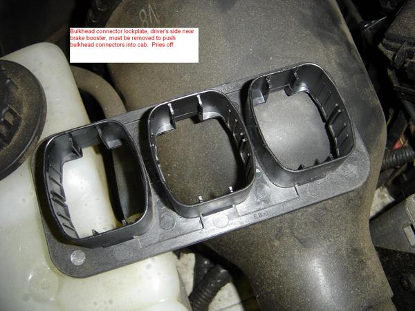
Disconnect the three connectors by loosening the 10mm bolts holding them in place, pry the black lockplate off and squeeze the locking tabs to release them from the firewall.
Temperature blend door removal
Back inside the vehicle...
Ford Instrument panel parts


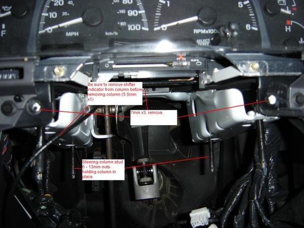
The driver's side after removal of the steering column. Disconnect the eleventy connectors going to various things on the steering column, turn the ignition switch to off and wiggle the steering wheel back and forth a little until it locks. This prevents the steering wheel from running off and damaging the clockspring. Now, unbolt the steering shaft pinch bolt (13mm), unbolt the shift indicator (5.5mm) and disconnect it from the shift lever, disconnect the column shifter cable and unbolt the column by removing the 6 - 13mm bolts holding it to the dash support. Also note the three 7mm bolts you'll have to remove to get the dash out as well. There's a 10mm nut on the lower left, and a couple grounds (8mm bolts) to remove in the driver's kickpanel. 
From down  pull the bulkhead connectors through into the cab that you disconnected from under the hood.
The passenger's side after removal of the airbag. The airbag is retained by one 8mm bolt under the oval shaped cover on top of the dash, and two 8mm bolts accessed through the glovebox. Note, do not unbolt the glovebox hinge to get to those bolts, just unclip it, fold it down, remove the bolts and snap it back into place. The glovebox is spring loaded and can be a pain to get back into place. There's four (or six, CRS, sorry) 7mm bolts you'll have to remove here. There's also a couple more grounds in the passenger's side kickpanel you'll want to remove, as well as connectors to things like the inertia switch, air suspension switch (if equipped), and blower motor amongst other things. This is also where I'd recommend going into the passenger's side front wheel well and disconnecting the antenna lead at the mast and shoving it through the firewall, this'll get you more room to work with when pulling the dash back.
The top of the dash. In an F150 or Expedition, it's got two or three little plugs that you've gotta pop out to get to the bolts.
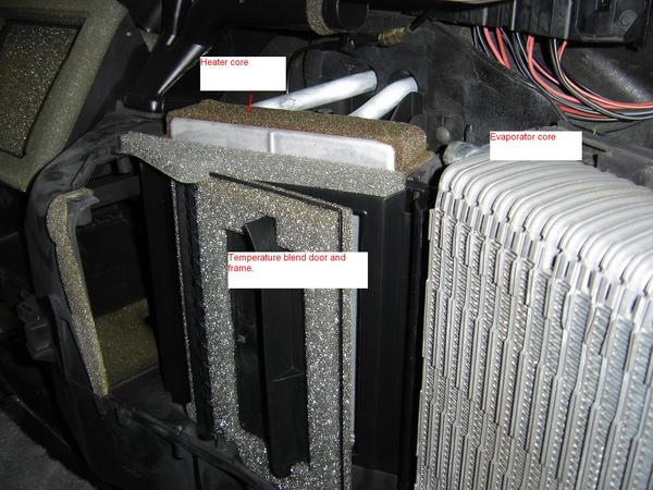
If everything goes as planned, you'll see something like this. This is the plentum chamber itself, where the evaporator core, heater core, and temperature blend door are. Let's crack that case open and see what's inside...15 - 8mm bolts...


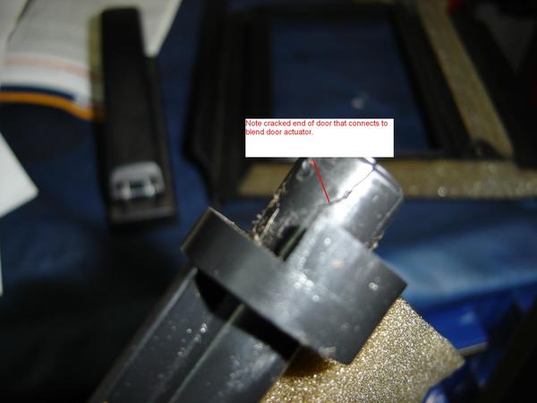
Pictured here are the evaporator and heater cores, and the blend door. The blend door is a snap fit into the case. Pull back on the frame of the door on the passenger's side of it and lift the whole shootin' match out.


This is the procedure.

@