@

max

Sunday

Pontiac Vacuum Hose Diagram

Vacuum Hose Pump Diagram Pontiac


For Complete Vacuum hose diagram

Fuel pressure regulator
Intake Manifold
PCV Valve
Brake Booster
EVAP Canister Purge Valve
Throttle Body

FOR PREVIOUS VACUUM HOSE DIAGRAM CLICK HERE


1996 3.8L (BRN) Engine-Federal and California:--
Pontiac Vacuum hose Diagram

-----------

1996 3.8L (BRG) Engine-Federal and California:--


1996 3.8L (BRF) Engine-Federal and California


Pontiac Vacuum hose line


This Details Will Help.

Ford Engine Wiring Diagram

Wiring Diagram Ford Engine Ignition


The wiring diagram shows details for ford crankshaft sensor,ignition coil,sparkplug firing order details and much more:

For Previous Wiring Diagram Click Here

-----------
Diagram number 2:---
Engine Ignition System Wiring Diagram

-----------
Diagram number 3:---
image

-----------
The firing order diagram:---
Ford Escape Ignition Spark plug Firing Order

-----------
NOTE:-- 

Ignition timing is controlled by the Powertrain Control Module (PCM). No adjustment is necessary or possible.


For Sparkplug Testing,gapping and replacement details

How To Replace Headlight Switch On Dodge Caravan

Dodge Caravan Headlight Switch


For Headlight Switch Removal Diagram Click Here

For Removal Procedure Follow Reading As Follows:
Disconnect the negative battery cable.

Remove the instrument cluster bezel.

Disconnect the electrical connectors from the headlight switch and the power mirror switch.

Remove the mounting screws securing the headlight switch bezel to the instrument cluster bezel.

Remove the headlight switch bezel from the instrument cluster bezel.


To install:

Install the headlight switch bezel to the instrument cluster bezel and install the mounting screws.

Reconnect the electrical connectors to the power mirror switch and the headlight switch.

Install the instrument cluster bezel and headlight switch bezel to the instrument panel.

Reconnect the negative battery cable. Test the headlight switch for proper operation.


Instrument cluster removal:---

REMOVAL & INSTALLATION

See Figures 1, 2, 3, 4, 5, 6, 7, 8, 9, 10, 11 and 12


dodge caravan instrument cluster removal

Fig. Fig. 1: To access the instrument cluster mounting screws, remove the lower bezel ...


lower bezel removal

Fig. Fig. 2: ... and the driver's side end cap ...


Click image to see an enlarged view

Fig. Fig. 3: ... to access the upper trim bezel screws. After removing all of the screws ...


Click image to see an enlarged view

Fig. Fig. 4: ... carefully pull the upper bezel from the instrument panel
  1. Disconnect the negative battery cable.


CAUTION
The models covered by this guide are equipped with a Supplemental Restraint System (SRS), which utilizes a driver and passenger side air bag. Whenever working near any of the SRS components, such as the impact sensors, the air bag module, steering column and instrument panel, disable the SRS, as described earlier in this section.


Click image to see an enlarged view

Fig. Fig. 5: Once the bezel is removed, the instrument cluster mounting screws can be removed (two on each side)
  1. Disable the air bag system.
  2. If equipped with a mechanical transmission range indicator, perform the following;
    1. Remove the lower steering column cover.
    2. Remove the knee blocker reinforcement panel from under the steering column.
    3. Remove the indicator cable loop.

      Click image to see an enlarged view

      Fig. Fig. 6: After the mounting serews are removed, reach behind the cluster and unplug the electrical connectors ...


      Click image to see an enlarged view

      Fig. Fig. 7: ... and remove the cluster from the instrument panel
    4. Remove the clip securing the gear shift cable end to the gear selector adapter.
    5. Pull the cable end from the gear selector.

  3. Remove the instrument cluster bezel.
  4. Remove the mounting screws securing the instrument cluster to the instrument panel.
  5. Rotate the top of the cluster outward.
  6. Disengage the wiring harness connectors from behind the cluster assembly.
  7. Remove the instrument cluster from the vehicle. If equipped with a mechanical transmission range indicator, carefully guide the range indicator cable and guide tube through the opening to avoid any possible damage.


Click image to see an enlarged view

Fig. Fig. 8: Instrument cluster mounting detail (models with a mechanical transmission range indicator)


Click image to see an enlarged view

Fig. Fig. 9: Range indicator cable mounting detail
To install:
  1. If equipped with a mechanical transmission range indicator, verify the free travel of the range indicator cable from P to 1 by gently pulling on the cable, then relaxing the cable. Do NOT snap the cable once it is pulled.
  2. Position the instrument cluster assembly into the instrument panel by leading the bottom of the cluster in first, plug in the wiring harness connector(s), and rotate upward. If equipped with a mechanical transmission range indicator, route the indicator cable and guide tube through the opening in the instrument panel.


Click image to see an enlarged view

Fig. Fig. 10: On models with a mechanical transmission range indicator, the cable must be accessed by removing the lower steering column cover. Remove the mounting fasteners, and lower the cover ...


Click image to see an enlarged view

Fig. Fig. 11: ... disconnect the parking brake cable ...


Click image to see an enlarged view

Fig. Fig. 12: and remove the reinforcement
  1. Install and tighten the instrument cluster mounting screws.
  2. Install the instrument cluster bezel.
  3. If equipped with a mechanical transmission range indicator, install the indicator cable and guide tube. Install the cable retaining clips.
  4. Install the knee blocker reinforcement panel.
  5. Install the lower steering column cover.
  6. Connect the negative battery cable.
-------------
for wiring diagram of tail light,turn signal light and hazard lights check the wiring diagram below:---
dodge caravan cluster board wiring diagram

Nissan Altima Fuel Pump And Assembly Replacing

Nissan Fuel Pump System


  1. Properly relieve the fuel system pressure.
  2. Remove the rear seat.
  3. Remove the fuel pump cover.
  4. Label and disconnect the electrical harness.
  5. Label and disconnect the fuel hoses.


Nissan Altima Fuel pump removal diagram

Fig. Fig. 5: The fuel pump assembly consists of the pump cover (1), cover gasket (2), electric fuel pump (1), and strainer (2)
One hose is a high pressure fuel input hose and the other is a low pressure return hose. Different hose clamps are used on each of the hoses.
  1. Matchmark the locking ring with the body for installation reference. This is to prevent overtightening of the locking ring.
  2. Remove the locking ring using a special lock ring tool.

It may be possible to use a large set of locking jaw pliers to loosen the lock ring. However, extreme caution must be used to not damage the plastic ring or strip the plastic threads.
  1. Remove the fuel pump and sending unit from the fuel tank.

To install:
  1. Inspect the sealing gasket and replace if damaged.
  2. Install the fuel pump and sending unit in the fuel tank.
  3. Install the locking ring by hand and tighten using a special lock ring tool.

It may be possible to use a large set of locking jaw pliers to tighten the lock ring. However, extreme caution must be used to not damage the plastic ring or strip the plastic threads. Tighten the locking ring until the matchmarks align.
  1. Connect the fuel hoses using the proper hose clamps for the high pressure and low pressure hoses.
  2. Connect the electrical harness.
  3. Install the fuel pump cover.
  4. Install the rear seat.

Please Note: It is important to note that the fuel filter should be replaced once a year. Luckily, it is very inexpensive and the process is quite simple. For the Nissan Altima, the fuel filter is part of the car’s fuel pump assembly.

TESTING


Electrical Test


Remove the fuel pump inspection cover to access the fuel pump electrical harness.

Turn the ignition switch OFF .

Disconnect the fuel pump electrical connector.

Measure the resistance between the fuel pump terminals. Resistance should be 0.2-3.0 ohms @ 55°F (23°C).

If resistance is not within specification, the fuel pump may be faulty.

If the fuel pump resistance is within specification, check fuel pressure.


Pressure Test

See Figures 6 and 7


Nissan Altima Fuel Pressure Testing

Fig. Fig. 6: Connect a fuel pressure gauge inline between the fuel filter and fuel feed line


Click image to see an enlarged view

Fig. Fig. 7: Fuel pressure can be checked using an inexpensive pressure/vacuum gauge

Properly relieve the fuel system pressure.

Connect a fuel pressure gauge between the fuel filter outlet and fuel feed hose.

Start the engine and read the fuel pressure.

Fuel pressure should be approximately 21 psi (272 kPa) a few seconds after the ignition switch is turned from OFF to ON .

Fuel pressure should be approximately 12 psi (213 kPa) with the engine idling.

Stop the engine and disconnect the fuel pressure regulator vacuum hose.

Plug the vacuum hose at the intake manifold and connect a hand operated vacuum pump to the pressure regulator.

Start the engine and note the fuel pressure as vacuum is applied and released.

Fuel pressure should decrease as vacuum increases.

If fuel pressure does not respond as specified, the fuel pressure regulator may be faulty.

If fuel pressure responds as specified, but fuel pressure is not within specification, the fuel pump may be faulty.


The fuel pressure regulator.

REMOVAL & INSTALLATION


See Figures 1, 2 and 3

Nissan Altima Fuel Pressure regulator

Fig. Fig. 1: On the Altima, the fuel pressure regulator is attached to the passenger's side end of the fuel rail by two bolts


Click image to see an enlarged view

Fig. Fig. 2: Fuel pressure is controlled by a vacuum line connected to the fuel pressure regulator


Nissan Altima Fuel Pressure line

Fig. Fig. 3: Always use a new O-ring when installing the fuel pressure regulator

Properly relieve the fuel system pressure.

Disconnect and cap the fuel return line at the regulator.

Disconnect the vacuum line from the regulator.

Remove the bolts securing the pressure regulator to the fuel rail.


Place a rag under the fuel rail to absorb any remaining fuel.

Remove the regulator from the fuel rail and discard the O-ring.


To install:


Install a new O-ring on the regulator and position it on the fuel rail.

Tighten the regulator securing bolts to 26-34 inch lbs. (3-4 Nm).

Connect the vacuum line to the regulator.

Connect the fuel return line to the regulator.

Pressurize the fuel system and check for leaks.

Ford Temperature Blend Door

How To Replace Ford Temperature Blend Door

Because of very less space to remove the bled door you have to  get in there to the plentum chamber, including the radio antenna lead on the passenger's side, and the three bulkhead connectors on the driver's side.

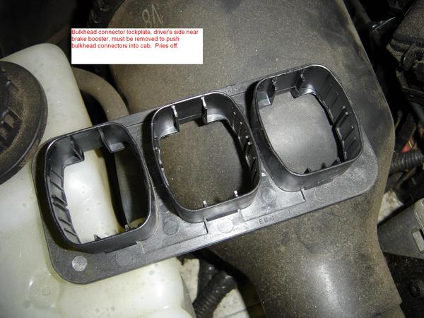
Disconnect the three connectors by loosening the 10mm bolts holding them in place, pry the black lockplate off and squeeze the locking tabs to release them from the firewall.
Temperature blend door removal
Back inside the vehicle...
Ford Instrument panel parts


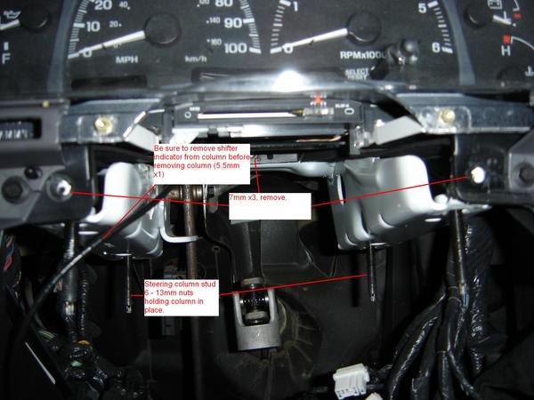
The driver's side after removal of the steering column. Disconnect the eleventy connectors going to various things on the steering column, turn the ignition switch to off and wiggle the steering wheel back and forth a little until it locks. This prevents the steering wheel from running off and damaging the clockspring. Now, unbolt the steering shaft pinch bolt (13mm), unbolt the shift indicator (5.5mm) and disconnect it from the shift lever, disconnect the column shifter cable and unbolt the column by removing the 6 - 13mm bolts holding it to the dash support. Also note the three 7mm bolts you'll have to remove to get the dash out as well. There's a 10mm nut on the lower left, and a couple grounds (8mm bolts) to remove in the driver's kickpanel. 
From down  pull the bulkhead connectors through into the cab that you disconnected from under the hood.
The passenger's side after removal of the airbag. The airbag is retained by one 8mm bolt under the oval shaped cover on top of the dash, and two 8mm bolts accessed through the glovebox. Note, do not unbolt the glovebox hinge to get to those bolts, just unclip it, fold it down, remove the bolts and snap it back into place. The glovebox is spring loaded and can be a pain to get back into place. There's four (or six, CRS, sorry) 7mm bolts you'll have to remove here. There's also a couple more grounds in the passenger's side kickpanel you'll want to remove, as well as connectors to things like the inertia switch, air suspension switch (if equipped), and blower motor amongst other things. This is also where I'd recommend going into the passenger's side front wheel well and disconnecting the antenna lead at the mast and shoving it through the firewall, this'll get you more room to work with when pulling the dash back.
The top of the dash. In an F150 or Expedition, it's got two or three little plugs that you've gotta pop out to get to the bolts.
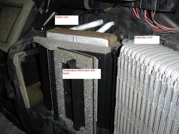
If everything goes as planned, you'll see something like this. This is the plentum chamber itself, where the evaporator core, heater core, and temperature blend door are. Let's crack that case open and see what's inside...15 - 8mm bolts...


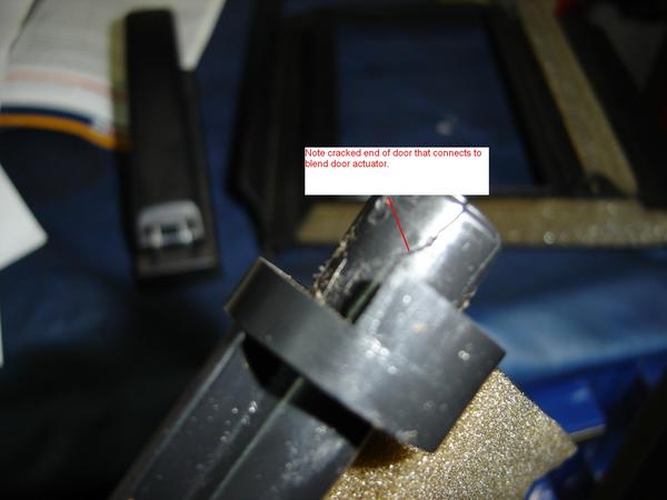
Pictured here are the evaporator and heater cores, and the blend door. The blend door is a snap fit into the case. Pull back on the frame of the door on the passenger's side of it and lift the whole shootin' match out.


This is the procedure.

How To Remove Dodge Liftgate

Dodge liftgate Assembly Removal


  1. Remove the outside liftgate handle and links from the vehicle.
  2. Remove the lock cylinder retaining clipfrom the door handle.
  3. Remove the door lock cylinder and arm from the handle. Do not remove the E-clip.
dodge caravan liftgate lock cylinder and clip removal

Fig. Fig. 2: Liftgate lock cylinder and retaining clip removal
To install:
  1. Engage the retaining clip into the liftgate handle.
  2. Push the lock cylinder into the handle until the clip engages the lock cylinder groove with an audible click.
  3. Position the outside liftgate handle and links onto the liftgate.
  4. Engage the retaining groove to hold handle to the liftgate by pushing the handle to the right for centering.
  5. Install nut to mount the outside liftgate handle to the liftgate.
  6. Connect the VTSS switch to the back of the lock cylinder and plug in wiring harness, if equipped.
  7. Engage the outside handle link to the clip on the liftgate latch.
  8. If equipped, install the lock link.
  9. Install the power lock motor.
  10. Verify lock cylinder and liftgate operation.
  11. Install the liftgate trim panel.
  12. Connect the negative battery cable.
-------------------------------------
Dodge Caravan Lift Gate
-------------------------
Door locks removal and installation:----

REMOVAL &INSTALLATION


See Figures 1 and 2
  1. Disconnect the negative battery cable.
  2. Remove the interior door panel and peel away the plastic sound shield to gain access to the door handle.
  3. Roll up the door glass.
  4. Through the access hole at the rear of the inner door panel, disengage the Vehicle Theft Security System (VTSS) switch connector from the door harness, if equipped.
  5. Remove the push pin fasteners securing the VTSS switch harness to the inner door reinforcement bar, if equipped.
  6. Disconnect the clip that retains the door latch linkage to the door latch.
  7. Separate the latch linkage from the latch.
  8. Disengage the clip retaining the door lock linkage to the door latch.
  9. Remove the lock linkage from the latch.
  10. Remove the nuts attaching the outside door handle to the door outer panel.
  11. Remove the outside door handle from the vehicle.
Dodge caravan door assembly

Fig. Fig. 1: Front door outside handle assembly removal
Dodge Caravan Door Lock Cylinder

Fig. Fig. 2: After removing the retaining clip, pull the lock cylinder straight out from behind the handle assembly
  1. Disengage the clip holding the lock cylinder into the outside handle.
  2. Remove the door lock from the door handle.

To inside:
  1. Engage the clip into the outside handle to hold the door lock cylinder.
  2. With the link arm positioned toward the rear of the vehicle, push the lock cylinder into the door handle until the clip snaps into place.
  3. Insert the lock linkage into the door latch.
  4. Engage the clip to hold door lock linkage to latch.
  5. Insert the latch linkage into door latch.
  6. Engage clip to hold door latch linkage to latch.
  7. Insert push pin fasteners attaching the VTSS switch harness to the inner door reinforcement bar, if equipped.
  8. Plug the VTSS switch connector into the door harness, if equipped.
  9. Verify door latch operation.
  10. Install the plastic sound shield and interior door panel.
  11. Connect the negative battery cable.


Dodge Durango Steering Wheel Removal

How To Replace Durango steering wheel


Dodge durango Rack and pinion gear

Fig. Rack and pinion steering gear mounting used on the 2WD 2002-03 models
Rack and pinion steering gear mounting used on the 2WD 2002-03 models


To install:
  1. Install or connect the following:

    Steering gear. Tighten the bolts to 190 ft. lbs. (258 Nm).
    Power steering hoses. Tighten the fittings to 25 ft. lbs. (35 Nm).
    Steering shaft coupler. Tighten the bolt to 36 ft. lbs. (49 Nm).
    Outer tie rod ends. Tighten the nuts to 65 ft. lbs. (88 Nm).                                                                               

Replacing Dodge Steering wheel

Steering Wheel Removal for dodge 


From the underside of the steering wheel, remove the two screws that secure the driver airbag to the steering wheel armature.

See the Airbag removal screw diagram shown below:

    Dodge Airbag removal from steering wheel

    Once you remove those, CAREFULLY pull the air bag out of the steering wheel.


    Pull the driver airbag away from the steering wheel far enough to access the three electrical connections on the back of the airbag housing.

    Disconnect the steering wheel wire harness connector for the horn switch from the horn switch feed pigtail wire connector, which is located on the back of the driver airbag housing


    WARNING


    Do not pull on the clockspring pigtail wires or pry on the connector insulator to disengage the connector from the driver airbag inflator connector receptacle. Improper removal of these pigtail wires and their connector insulators can result in damage to the airbag circuits or connector insulators.

    The clockspring driver airbag pigtail wire connectors are secured by integral latches to the airbag inflator connector receptacles, which are located on the back of the driver airbag housing. Depress the latches on each side of the connector insulator and pull the insulators straight out from the airbag inflator to disconnect them from the connector receptacles.

    Remove the driver airbag from the steering wheel.

    If the driver airbag has been deployed, the clockspring must be replaced.

    Partially remove the steering wheel bolt and leave the bolt in the column.

    Install puller CJ98-1 or equivalent using the top of the bolt to push on.

    Remove and discard the steering wheel bolt.

    Remove the steering wheel.

    See below Image Showing Steering Wheel Removed:

Dodge Durango Steering Wheel Disassembled

@